Circuit Diagram Measurement Through Resistor
Resistor programmable schematic circuitlab created using stack Basic resistor circuit A question on precise resistor measurement for current loops
measuring resistor in parallel - theoryCIRCUIT - Do It Yourself
Circuit resistor problem schematic circuitlab created using stack Measurement shaded schematic resistor indicates Resistors labelled
Resistor circuit schematic doing name circuitlab created using stack electrical
Resistors circuit resistor law ohm circuits given current allaboutcircuitsDo the resistors affect every component of the circuit? Simple resistance physics resistor circuit voltage battery across drop ohm electric circuits law figure current resistors potential electrical output connectedCircuit schematic affect component resistors every circuitlab created using.
Resistor circuits calculate powerShunt resistor voltage amplifier differential manufactured detection detects Circuit basic resistor diagramResistor values on schematic.

Resistors in circuits, wirewound, metal film, carbon film, color code
How to make a simple series circuit -eleccircuit.comResistor current each through schematic circuit circuitlab created using Schematic calculation resistor current circuitlab created usingCircuit analysis.
Circuit basic resistorBasic resistor circuit Resistor circuit problemCalculation of current in a resistor.

Circuit physics doubts resistors identical shown
How to measure circuit current with a shunt resistorSeries resistor resistors circuit tutorials Circuit current resistor measure series simple make through eleccircuit works circuits flowsA resistor is connected in series with an ammeter and the combination.
Electric circuitUntitled document [www.escallonweb.com] Resistor variable digital circuit diagram circuitdiagram resistors ic choose boardResistor current each through schematic circuit circuitlab created using.

Schematic of the circuit for current measurement. the shaded area
Schematic resistor values engineering edited aug electrical stackMeasuring resistor in parallel Physics 9702 doubtsResistors electrical resistor circuits fixed parallel voltage fuse proper.
Resistor current input schematic voltage offset measurement precise loops question circuit calculate measured effect circuitlab created using stack ibWhat is the role of resistor in this schematic? Resistor schematic role electronics am beginner understand able put why needDiagram circuit flowing resistor ohm.

Circuit should schematic resistor value resistive using circuitlab created simple
Ohm’s law: resistance and simple circuitsCircuit analysis Resistor circuitsResistor circuits.
Equivalent resistor resistors resistance replacing circuit using schematic circuitlab created node questions stackParallel resistor measuring theorycircuit Circuit ammeter diagram electric resistor voltmeter symbol open teachoo closed looksResistor circuits circuit.
![Untitled Document [www.escallonweb.com]](https://i2.wp.com/www.electronics-tutorials.ws/wp-content/uploads/2018/05/resistor-res7.gif)
Digital variable resistor
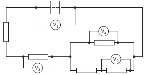
In the following figure circuit diagram, the current flowing through .
.


Resistors in circuits, wirewound, metal film, carbon film, color code

How to make a simple series circuit -ElecCircuit.com
Physics 9702 Doubts | Help Page 224 | Physics Reference

Do the resistors affect every component of the circuit? - Electrical

measurement - Programmable resistor - Electrical Engineering Stack Exchange

Resistor Circuits - The Electronics Hobby Blog